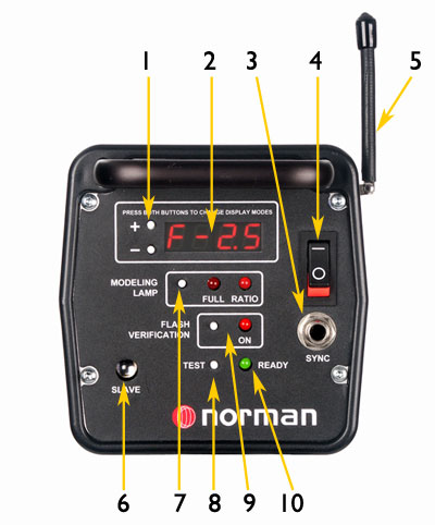
ML400 & ML600 Control Panels
1- Control Switches: Set Power level in 1/10 stop increments. Also select display mode in f/stops or watt-second.
2- Digital Display: Shows selected power level in either f/stops or watt-seconds from full power.
3- Sync Outlet: A sync cable connects to this outlet for direct tripping from camera.
4- Power Switch: Switches AC power. Internal memory retains settings.
5- Radio Receiver: The optional built-in PocketWizard™ receiver triggers the flash from remote transmitter.
6- Photo Eye: Permits remote trigger from another flash unit, without the need for a sync cable.
7- Modeling Lamp Control: Selects off, full or ratio. In ratio mode the lamp tracks with flash power settings.
8- Test Button: Manually triggers the flash.
9- Flash Verification: When selected, the modeling lamp switches on and off to confirm the unit has flashed.
10- Ready Light: Illuminates when unit is fully charges and ready to be triggered.